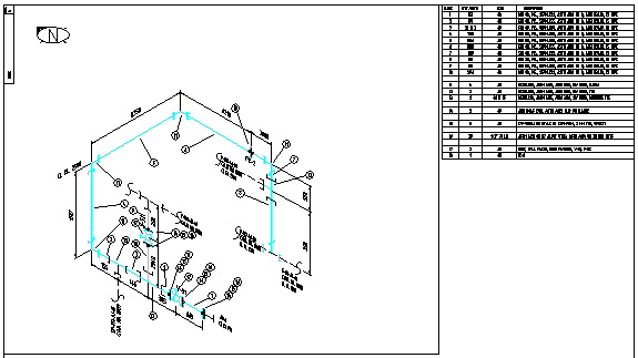
Pipe fitting insertion points are always located at the intersection of the pipe centerline. The symbols are also sized to snap to a grid with a 1/16? Snap Y Spacing. Once inserted, the symbols will take on the characteristics of your current layer settings. Accessories, such as mono flanges and double blocks, etc.Each symbol is drawn on layer zero with “bylayer” attributes. Tagging of all elements, fittings and valves Tagging of mechanical to instrumentation interface
Direction of slopes in the hookup lines Layout, routing and isometric piping drawings They detail the typical installation of a process or field instrument in the correct manner, so that once fitted, it can operate properly and prevent adverse issues affecting the measurements, such as liquid trapped in a gas impulse measuring device.Ī hookup diagram details the accessory and tubing hook up for instruments, including standard specifications for the welding of hookup piping, pressure testing, painting requirements, heat tracing and installation. Hookup diagrams are also referred to as installation drawings.
In order to find the best software for your needs, have a look into the benefits and drawbacks as well as the overall functions of the software. However, this is not a definitive guide, and there are a number of other software options for example AutoCAD. No online version available and only supported by Windows Complex software not suitable for beginners Depending on use, licensing can be expensive The free online version contains watermarks on the diagrams Supports Windows, Mac, Linux and the Web

You can grasp an understanding of the over system from all the processes within it. Once you’re familiar with the common symbols, abbreviations and diagram basics you can begin to understand the overall P&ID.Ī typical method used to read a diagram is line tracing - following the line from the input to the output reading the components and measurements along the way. The arrows between components also show the direction of flow in the system. They are depicted by the lines entering and leaving the component - e.g. All of our original symbols were in MicroStation cell library format. No dividing line - the instrument is suitable for field application.Ĭontrol Signals for components show their input and output - e.g. A good example of this is an isometric drawing, where the user must be in. The shape of the symbol may also provide vital information on the process.įor circular symbols, the dividing line suggests the type of mounting used for the device.Ĭontinuous dividing line - the instrument is suitable for control room mounting.ĭotted dividing line - the instrument is suitable for technical room mounting. Instrumented Protective System/ Fire & Gas System Abbreviations Basic Process Control System Abbreviations


 0 kommentar(er)
